Skip to content
LEANODM
Menu
Page Sections

MANUFACTURING / XINYINHAI FACTORY

Product Assembly & Packaging

Electronic product assembly, controlled screw fastening and hand soldering—connected to in-process inspection and final packaging.

This page presents Xinyinhai’s documented assembly and packaging methods for plastic and electronic OEM/ODM projects. Work instructions, trained operators and reference samples guide component fitting, process checks and preparation of the finished product.

COMPONENTS → FINISHED PRODUCTASSEMBLY / QC / PACKING
Illustrative exploded assembly and packaging sequenceAn abstract upper shell, insert, spring and fasteners align above a lower shell. A small assembled object and checked package explain the relationship between assembly and packing. This is explanatory geometry, not a product drawing or factory equipment.
Illustrative assembly geometry · not a product drawing
Defined work instructionsReference sample checksInspection before packingSee original process photographs

01 / ONE CONNECTED PROCESS

From Production Order to Finished Product

Assembly and packaging follow a planned route: prepare the line, confirm the first piece, train the operator, verify the work and inspect the packed result.

PREPARE / CONFIRM BEFORE START

  1. Order & production plan

    Start from the ERP production order and planned work.

  2. Instructions & tooling

    Prepare the work instructions, fixtures and required references.

  3. Materials & setup

    Issue the planned materials; arrange the line and confirm machine setup.

  4. First piece & training

    Confirm the first piece, then brief operators on the instruction and past issues.

PRODUCE / CHECK THROUGHOUT THE ROUTE

  1. Assembly operations

    Fit components; fasten, lubricate or hand-solder as the product requires.

  2. Self-check & line inspection

    Operators check their work; line patrol checks verify the running process.

  3. Quality verification

    OQC checks function and appearance against the applicable criteria.

  4. Packing & final acceptance

    Follow the packing route, final quality checks and accepted-goods handoff.

NG → identify, segregate, correct and re-check

The assembly board returns repaired units to the assembly sequence. Rejected packing returns for review and correction before acceptance.

Summarized from the assembly and packaging production boards. The product’s operations, inspection criteria and required customer inspection are confirmed for each project.

Follow the packaging route

02 / DEFINED AT THE WORKSTATION

Standardized Assembly Instructions

Work instructions make the order of operations and the expected result explicit. Operators use written steps and a reference sample to guide the assembly.

01

Component positioning

What happens
Place components in their defined slots and locating features.
What is controlled
Seat the spring firmly and flat; compare its position with the reference sample.
Why it matters
Establishes the starting position for the mechanism.
02

Mechanical fitting

What happens
Fit the locking part and bring the housing sections together.
What is controlled
Use the locating slot and align the upper and lower housings before closing.
Why it matters
Supports correct fit and mechanical engagement.
03

Fastening

What happens
Secure the housing with screws in the specified sequence.
What is controlled
The documented example starts at the locking side, then secures the remaining positions.
Why it matters
Makes the fixing sequence explicit to the operator.
04

Functional assembly

What happens
Lubricate the specified sliding surfaces and fit the internal component.
What is controlled
Keep product surfaces clean; check retention, locking and movement at inspection.
Why it matters
Connects component fitting to the finished product’s operation.
A documented multi-step assembly example

The archived work instructions connect six assembly and packing operations with a separate inspection instruction. They demonstrate a defined sequence, reference-sample checks and cleanliness requirements.

  1. ComponentsPlastic parts, springs and fixing components
  2. Mechanical assemblyLocate spring, fit lock, align housings
  3. FasteningSecure the housing in the defined order
  4. LubricationApply at specified sliding surfaces
  5. Functional assemblyFit the internal component into the body
  6. Final QCCheck appearance, engagement and movement
  7. PackingBag, arrange and place in cartons

03 / THE DETAILS THAT MATTER

Assembly Control Points

Correct assembly depends on both the position of the parts and the condition of their interfaces. These control points recur across the work instructions and inspection requirements.

ASSEMBLY INTERFACES01—07
Seven assembly control points on illustrative geometryNumbered callouts identify component positioning, clean surfaces, secure engagement, fastening, lubricant at designated moving locations, reference sample comparison and smooth operation. The abstract housing and mechanism show concepts, not dimensions or measured performance.01020304050607
Illustrative assembly geometry · not a product drawing

Numbers connect the illustrative interfaces to the documented control points.

  1. 01

    Correct positioning

    Defined slots and locating features establish where each part belongs.

  2. 02

    Clean surfaces

    Maintain cleanliness during lubrication and internal assembly.

  3. 03

    Secure engagement

    Fit the lock correctly and verify that the mechanism holds in position.

  4. 04

    Proper fastening

    Follow the housing fixing sequence in the work instruction.

  5. 05

    Specified lubrication

    Apply lubricant where the instruction identifies a moving or sliding surface.

  6. 06

    Reference sample conformity

    Use the reference sample alongside the written instruction.

  7. 07

    Smooth operation

    Check opening, closing and retention on the assembled product.

04 / TOOLS, FIXTURES & TORQUE

Screw-Fastening Controls at Xinyinhai

Manual electric screwdrivers and automatic screw machines share the same priorities: the correct screw, stable positioning, verified torque and a defined response when fastening is abnormal.

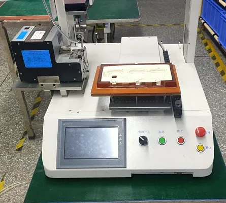
Archived single-workstation screw machine showing its fixture, feeder and control panel
Single workstationOne product position, with the screw feeder and fixture beside the driver.
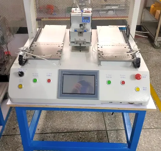
Archived automatic screw machine with two fixture positions and front controls
Dual workstationTwo work positions shown in the automatic-fastening training material.

MANUAL + AUTOMATIC METHODS

Match the method to the joint.

The training covers handheld electric drivers, single-head machines with one or two workstations, and a dual-head / dual-workstation configuration.

Fixture location, screw access, driver-bit fit and suction-nozzle condition matter alongside the torque setting.

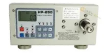
Digital torque tester illustrated in the screw-fastening training guide
Torque tester: training equipment reference.

Verify the setting

Torque-checking equipment and inspection records support the tool check. Set values and checking frequency follow the product-specific instruction.

Machine photographs are archived factory process evidence. They illustrate documented configurations; project equipment allocation is confirmed during review.

Fastening control loop

  1. 01Correct screw
  2. 02Locate in fixture
  3. 03Verify torque
  4. 04Check tool & nozzle
  5. 05Fasten & inspect
  6. 06Respond to alarm
  7. 07Segregate NG
  8. 08Correct & re-check

What the checks address

Missing, loose or raised screws; wrong or mixed screw types; damaged heads; incorrect torque; contaminated feeders; poor fixture alignment; and operator handling errors.

When a result is abnormal

Mark the affected position, separate the unit for the line leader’s review and investigate the screw, tool, fixture and molded fixing feature. Confirm the affected fasteners again after correction.

Tool setup, alarms, feeding and line clearance
Tool and fixture checks
Use the specified screw, compatible driver bit and suction nozzle. Check wear, straightness and product seating; a damaged bit or unstable fixture can affect fastening.
Machine controls and alarms
Train operators on reset, start, stop and emergency-stop controls for the specific machine. The guide includes missed-pickup and torque alarms, marked NG units and separate collection for review.
Screw loading and clearance
Match the screw type and feeder before loading. Follow the prescribed power-off procedure for loading or removing screws. Check the hopper, turntable and rails for hidden screws when clearing the feeder.
Cleaning and verification
Remove loose screws and debris from the feeder, fixture and machine surfaces. Review tool condition, screw seating and affected fastening positions; do not treat an alarm reset alone as product acceptance.
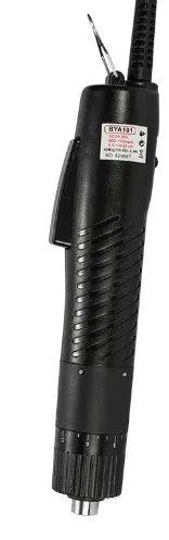
Handheld electric screwdriver shown in the fastening training guide
Manual electric driverTraining equipment reference.
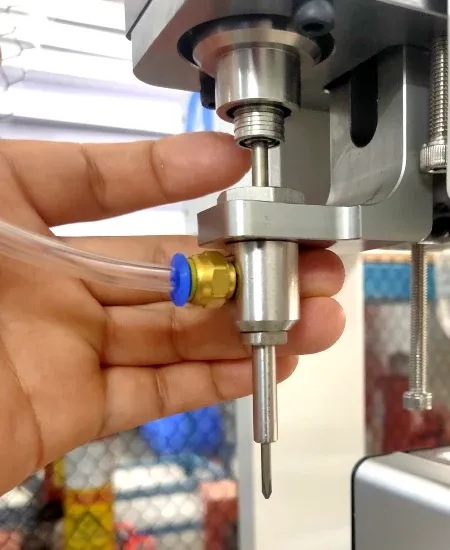
Hands showing the screw-machine suction nozzle and driver bit assembly
Nozzle & bitArchived tool-check photograph.
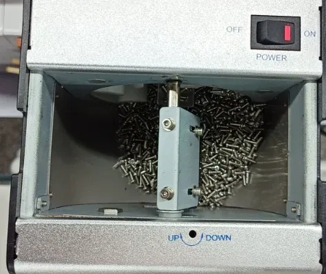
Loose screws in the hopper of the automatic screw feeder
Feeder hopperArchived screw-feeding photograph.

05 / ELECTRONIC CONNECTIONS

Hand-Soldering Controls at Xinyinhai

Hand-soldering assembly is controlled through cleanliness, temperature and time. Preparation, trained handling and visual joint checks connect the operation to the product’s acceptance requirements.

01Cleanliness
Prepare clean component leads and pads. Check the tip for residue, oxidation or damage so the contact surfaces can wet correctly.
02Temperature
Select suitable iron power and tip contact area. Allow the setting to stabilize, then verify tip temperature with the tester.
03Time
Control heating, solder feeding and withdrawal. Keep the connection undisturbed while the solder solidifies.
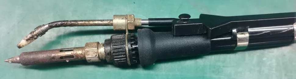
Manual solder-feeding irons and tips pictured in the assembly training material
Controlled hand feedingSolder-feeding irons illustrated in the training guide.
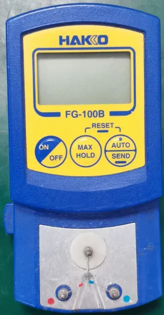
Soldering-iron temperature tester with its measurement sensor
Verify tip temperatureTraining equipment reference; no measured result is implied.
FIVE-STEP HAND-SOLDERING SEQUENCEAFTER CLEANING & TEMPERATURE VERIFICATION
  1. 01

    Heat the joint

    Bring the tip into contact with the component and pad.

  2. 02

    Feed solder

    Feed at the heated joint with a controlled amount.

  3. 03

    Withdraw solder wire

    Stop feeding when the required solder amount is reached.

  4. 04

    Continue heating

    Observe the forming joint for the specified brief period.

  5. 05

    Withdraw the iron

    Remove smoothly; keep the joint still as it solidifies.

Sequence redrawn from the training guide. Heating time and temperature follow the product-specific work instruction.

GOOD / NG TRAINING REFERENCES

Recognize the joint, then check the requirement.

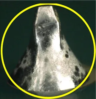
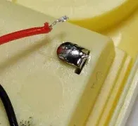
Compare solder amount, joint profile, wetting and wire engagement with the work instruction. The examples show acceptable appearance and a poor wire connection; they are different training examples, not a before-and-after pair.

  • Excessive or insufficient solder
  • Bridging and solder spikes
  • Cold / poorly formed joints
  • Loose or poorly soldered wire
  • Oxidation and poor wetting
Acceptable solder-joint training close-up with the original yellow inspection circle
GOOD / reference appearanceJoint identified as acceptable in the training guide. Apply the project’s acceptance criteria.
Poor wire-soldering training example showing a red wire separated from its soldered contact
NG / poor wire connectionWire connection identified as poor in the guide. This is not a current production incident.
Tip selection, heating technique and maintenance

Transfer heat at the interface

Choose the tip shape and contact area for the connection. Heat both the component and copper pad; control solder feeding at the heated joint and withdraw the iron smoothly.

Keep the tool and fixture clean

Inspect tip condition, remove residue with the specified cleaner, protect the tip during pauses and switch off for extended idle periods. Clean fixtures so debris does not transfer to the product.

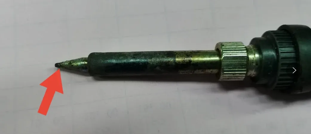
Soldering tip before cleaning in an archived training photograph
Before cleaningResidue on the tip is highlighted by the original training arrow.
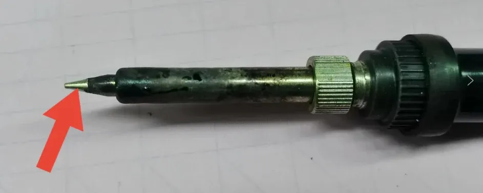
Soldering tip after cleaning in the matching archived training photograph
After cleaningThe guide pairs tip cleaning with temperature and joint-surface checks.

Temperatures, heating times and any electrical or mechanical tests are defined for the product. Training photographs do not establish a test result or a universal solder-joint acceptance standard.

06 / ASSEMBLY → QC → PACKING

How Assembly Quality Is Verified

Quality checks begin before batch work and continue through assembly. First-piece confirmation, operator self-checks and line inspection lead into final quality verification before packing.

BEFORE PRODUCTION

First-piece confirmation

Confirm setup and the initial product against the instruction and reference before the trained operator starts the run.

DURING PRODUCTION

Self-check + line patrol

Check the operation as it runs. Review fastening, soldering, component fit and cleanliness at the relevant process.

BEFORE ACCEPTANCE

Quality verification

OQC checks appearance and function. Identify and segregate NG units; return repaired units for the required re-checks.

INSPECTION & PACKING CHECKPOINTSPRODUCT-SPECIFIC REQUIREMENTS
FINAL QC

Appearance

  • Component color and transparency
  • Visible defects and surface cleanliness
  • Scratches and stress whitening
  • Flash and burrs
  • Printing accuracy and clarity
FINAL QC

Assembly

  • Correct component positioning
  • Correct housing fit
  • Secure mechanical locking
FINAL QC

Function

  • Smooth opening and closing
  • Reliable mechanical engagement
  • Retention of the intended component
AFTER QC

Packing

  • Clean finished product
  • Bagging to the work instruction
  • Organized placement
  • Neat arrangement in finished-goods cartons
Reference sample + written criteria

The checklist identifies what is checked. It is not a test report or a universal acceptance specification.

07 / SMALL PARTS, CLEAN WORK & CLEARANCE

Foreign-Object Prevention in Assembly & Packaging

The objective is to reduce unintended material entering the product or package. Hazard awareness, workstation cleaning and feeder clearance support the self-check, line inspection and final verification route.

Process residues

Loose screws, metal chips, solder debris, plastic runners or fragments, paper scraps and transparent tape.

Small parts & tools

Batteries, rubber bands, other loose parts, driver bits, blades, needles and tools that could remain inside a package.

Handling & environment

Hair, fibers or cleaning-cloth fragments, insects, glue strands and surface contamination.

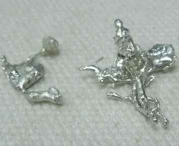
Solder residues used as a foreign-object hazard example in the packaging training material
Solder residuesOriginal training example of loose process debris.
Paper scraps inside a carton in a packaging contamination training example
Packaging scrapsOriginal training example; not a current shipment incident.

Clear the source of debris

The screw-machine guide requires removal of remaining screws from the feeder and rails, followed by cleaning of the machine surface. Soldering training adds tip and fixture cleaning.

Define the final check

The project packing checklist should specify visual checks inside the product and package, tool and sharp-object control, and removal of loose materials before closure. Inspection follows the agreed criteria.

The awareness board’s “zero-risk” wording is an internal prevention objective. It is not a guarantee of zero foreign objects or zero defects.

08 / THE FINAL PRODUCTION CONTROL

Packaging & Final Verification

Packaging connects material preparation, clean handling, product protection and inspection. The documented route ends with accepted-status identification and a controlled handover to finished-goods storage.

PACKAGING ROUTE / PREPARATION TO ACCEPTED GOODS

  1. Prepare & inspect

    Issue packaging materials against the production plan. Include the BIQC gate where applicable.

  2. Set up & confirm

    Confirm the packing line, equipment setup and first piece; train operators before starting.

  3. Pack & self-check

    Use the defined bagging and placement method. Operators check work during packing.

  4. Inspect the running line

    Line patrol and Quality sampling check the packing operation and finished output.

  5. Final verification

    Keep finished goods in the designated area for required final and customer inspection.

  6. Identify & hand over

    Apply accepted status identification and complete warehouse handover for shipment readiness.

Rejected packing returns for correction

Quality and required customer-inspection decisions feed back to the packing operation. Complete the relevant verification before accepted-goods handover.

DEFINE IN THE PROJECT PACKING INSTRUCTION

Make the packed configuration explicit.

The archived SOP establishes bagging, orderly placement and carton packing. Extend that basis with the product-specific requirements below.

  • Correct product, components and accessories
  • Clean packaging materials and product surfaces
  • Required bag, insert and protective arrangement
  • Label / artwork revision and packed quantity
  • Carton arrangement and condition
  • Foreign-object check and final acceptance criteria

The board includes a BIQC inspection gate; its scope follows the applicable product route. Customer inspection is included when required. These stages do not imply a universal 100% inspection or shipment guarantee.

09 / ORIGINAL PROCESS PHOTOGRAPHS

Documented Assembly in Practice

Selected photographs from archived factory work instructions show the actual assembly operations behind the process. They complement the equipment and training references above and illustrate the method, rather than the current factory layout or product range.

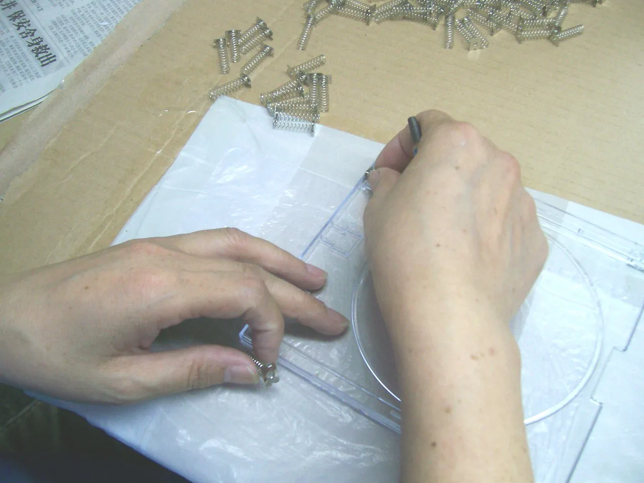
Operator positioning a metal spring in the locating slot of a clear plastic housing
COMPONENT POSITIONING

A defined position for the spring

The instruction requires installation in the locating slot, pressed firmly and flat, with the sample as a reference.

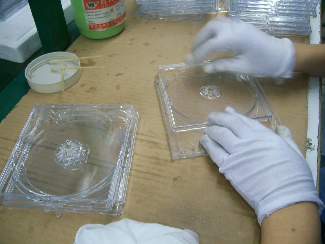
Gloved operator applying lubricant to the sliding rail of a clear internal component
LUBRICATION & CLEANLINESS

Specified surfaces, clean handling

The instruction identifies the sliding rail for lubrication and requires product surfaces to remain clean.

10 / WHAT THE BUYER RECEIVES

Why Assembly Discipline Matters

Assembly decisions affect how a product looks, fits, moves and arrives at the packing stage.

01

Cosmetic quality

Clean handling and appearance checks address marks, contamination and visible defects.

02

Mechanical fit

Locating features, housing alignment and fastening define how parts come together.

03

Moving performance

Specified lubrication and functional checks address sliding, opening and locking.

04

Product consistency

Written steps and a reference sample give operators a common assembly basis.

05

Final presentation

Print clarity, clean surfaces and orderly handling matter to the finished appearance.

06

Packing readiness

The process connects inspection with bagging, placement and carton packing.

11 / OEM & ODM PROJECT FIT

Suitable Project Types

Start with the component set and required operations. The same assembly discipline can inform different product briefs; suitability is confirmed through technical review.

Plastic products & mechanical assemblies

Projects with molded housings, internal parts, springs, locks, screws or moving interfaces.

Electronic products with assembled housings

Plastic and electronic OEM/ODM products within the factory’s manufacturing scope. Electronic integration and testing requirements are reviewed separately.

Promotional, gift & interactive product briefs

Potential applications to assess against the design, components and acceptance requirements. These examples do not imply an available product catalogue.

Review project fit & working principles

12 / CONNECTED MANUFACTURING

How Assembly Connects With Xinyinhai’s Manufacturing

Review the adjacent capabilities and quality requirements when defining the complete manufacturing scope.

Review the OEM manufacturing scope How project review and production connect

ACTIVITIES & COMMUNITY

Assembly teams and their working environment

Factory records offer a closer look at assembly workspaces, learning and team life.

13 / BUYER QUESTIONS

Assembly & Packaging FAQ

Practical answers for sourcing, engineering and quality teams reviewing contract assembly services for plastic and electronic products.

What assembly methods are documented at Xinyinhai?

Xinyinhai’s documented assembly and packaging methods support plastic and electronic OEM/ODM project review. These include component positioning, housing and mechanism fitting, manual and automatic screw fastening, hand soldering, specified lubrication, inspection and packing. The component set, connection method and required tests are reviewed against each project’s drawings, specifications and reference samples.

How do you control screw torque during assembly?

The fastening training includes electric-driver adjustment, torque-checking equipment and torque inspection records. Operators also check fastening condition, including missing or raised screws. The torque requirement, checking method and frequency must be defined for the product and fixing materials; an example machine setting is not a universal assembly specification.

Do you support both manual and automatic screw fastening?

Yes. The documented methods include handheld electric screwdrivers and automatic screw machines, with single- and dual-workstation configurations. Machine selection depends on screw access, fixture design and product requirements. Setup includes the correct screw, compatible driver bit and suction nozzle, fixture positioning and torque verification.

How do you control hand-soldering quality?

The training centers on cleanliness, temperature and time. Operators select a suitable tip, verify tip temperature after stabilization, heat the component and pad, control solder feeding and withdrawal, and leave the joint undisturbed during solidification. Visual checks address solder volume, bridging, spikes, poor wetting and wire engagement. Temperature, timing and any electrical or mechanical tests are project-specific.

How do you prevent foreign objects from entering finished packages?

Packaging awareness materials identify loose screws, metal and solder debris, plastic offcuts, paper and tape, personal contamination, small parts and tools as risks. Screw-machine instructions require feeder and rail clearance and removal of debris. These controls connect with operator self-checks, line inspection and final quality verification. The project packing checklist should define tool control and checks inside the product and package; the objective is risk reduction.

How is first-piece and in-process inspection handled?

The production boards place setup and first-piece confirmation before operator training and the start of assembly or packing. During operation, self-checks and line patrol checks feed into quality verification. The assembly route includes OQC checks of function and appearance; the packaging route includes BIQC where applicable and final quality sampling. Acceptance criteria and inspection frequency follow the project requirements.

How are nonconforming assembly units controlled?

The screw-fastening guide requires the affected location to be marked, the unit to be placed in a separate collection container, and the line leader to confirm the issue and arrange handling. The assembly board routes repaired units back through the assembly sequence. Rework requires the relevant checks again before the unit returns to the accepted flow; rejected packing also returns for review and correction.

Can assembly instructions be customized for each product?

Assembly requirements are reviewed for the specific product: component positions, sequence, fixture, screw type and torque, soldering conditions, functional checks and packing method. The documented SOPs show how work steps and reference samples connect to inspection. Provide drawings, a component list, acceptance criteria and packaging specifications so the project instruction can be defined.

How do you control assembly consistency?

Work instructions define component locations, housing alignment, fastening sequence, lubrication points and cleanliness requirements. Operators refer to the reference sample as well as the written steps. These instructions connect the assembly sequence to the product’s inspection requirements.

Do you perform inspection before packaging?

Yes. The documented assembly flow places QC after internal component assembly and before bagging and carton packing. Inspection covers appearance, printing, locking, opening and closing, and retention. Packing instructions then define bagging, organized placement and carton packing.

Can assembly and packaging be included in an OEM/ODM project?

Yes. Assembly and final packaging can form part of an OEM/ODM manufacturing scope alongside product development and plastic molding. The component set, assembly method, reference sample, acceptance criteria and packing requirements need to be confirmed for the project.

How do you control cosmetic defects during assembly?

The assembly instructions require clean surfaces during lubrication and internal component fitting. Final inspection checks visible defects, scratches, stress whitening, flash, burrs, color, transparency and printing accuracy and clarity against the applicable requirements and reference sample.

How do you verify moving or locking components?

The documented inspection checks that the internal assembly locks securely, opens and closes smoothly, and retains the component it is intended to hold. These are product-specific functional checks; the required motion, engagement and retention criteria are defined for each project.

Can you manufacture, assemble and pack products in one factory?

Xinyinhai’s documented capabilities connect plastic injection molding with assembly, inspection and packing. Whether a complete product can follow that route depends on its materials, components, finishing and test requirements. The manufacturing scope and any external operations are confirmed during project review.


YOUR NEXT OEM / ODM PROJECT

Prepare Your Assembly & Packaging Requirements

Bring the component fit, assembly sequence, fastening, soldering, inspection criteria and packaging requirements into one project brief.

Use this checklist to prepare your project review or quote request. Downloading it does not submit an enquiry.

Prepare for an assembly review

  • Drawings, component list and material specifications
  • Reference sample and required assembly sequence
  • Screw type, torque, fixture and fastening requirements
  • Soldered connections and acceptance requirements
  • Appearance, functional checks and inspection criteria
  • Accessories, protection, quantity, labels and carton arrangement
  • Target quantity and intended market